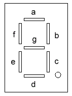
Introduction to seven segments display:
The segments in a 7-segment display are arranged to form a single digit from 0 to F. We can display a multi-digit number by connecting additional displays. Even though LCD displays are more comfortable to work with , 7-segment displays are still standard in the industry. This is due to their temperature robustness and visibility.
The segments in a 7-segment display are arranged to form a single digit from 0 to F. We can display a multi-digit number by connecting additional displays. Even though LCD displays are more comfortable to work with , 7-segment displays are still standard in the industry. This is due to their temperature robustness and visibility.
Segments are marked with non-capital letters: a, b, c, d, e, f, g and dp , where dp is the decimal point. The 8 LEDs inside each display can be arranged with a common cathode or common anode. With a common cathode display, the common cathode must be connected to the 0V rail and the LEDs are turned on with a logic one. Common anode displays must have the common anode connected to the +5V rail. The segments are turned on with a logic zero. 7-segment displays come in different colors, including: red,orange, and green.
Interfacing :
1- use a display driver such as the 7447 IC which convert the BCD number to it's seven segment code with the PIC (number of pins used is 4 ).
2- Alternatively displays can be driven by a micro-controller (number of pins used is 7 plus the decimal point ).
3- use 7447 with a decade counter (counter counts from 0 to 9) with the microcontroller (uses one pin but is not so fast) More Details
Multiplixing :
if more than one display is required, the method of driving them is called "multiplexing." The main difference between the two methods is the number of "drive lines." If a single display is to be driven from a micro-controller, 7 lines will be needed plus one for the decimal point. For each additional display, only one extra line is needed.
Each display is turned on at a rate above 100 times per second, and it will appear that all the displays are turned on at the same time. As each display is turned on, the appropriate information must be delivered to it so that it will give the correct reading. Up to 6 displays can be accessed like this without the brightness of each display being affected.
The following truth table shows the seven segment code for each number from 0 to 9
when we used common anode seven- segment:Keypad :
It's an array of switches such as the following figure :
This is an example of a 3x4 keypad to connect it to the micro-controller it needs 12 digital pins !! which is a large number .
Scanning keypad :
To decrease the number of digital pins required . the keypad is divided into 3 columns and 4 rows only one column is enabled at a time for example column 1 is enabled by connecting it to 5v . if button 1is pressed then A will be high ,if button 4 is pressed then B will be high and so on then column 2 is enabled and then column 3 is enabled and this sequence is repeated very fast so it appears that it's scanning all the 12 buttons but in fact it scans only four buttons at a time in this manner we decrease the number of digital pins to 7.
The next program scans a keypad and the key pressed is dissplayed on the seven segment display .the microcontroller used is PIC16f877A .
The keypad is connected to PORTC and the 7447 driver is connected to PORTB as shown.


PIC 16f877a with Seven-Segment Display and keypad